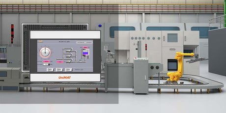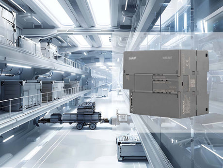
IM267 is a distributed communication interface module developed by UniMAT Automation for system integration customers. Support Profinet slave communication protocol, 100Mbps communication rate makes your device fly. It has the function of Ethernet communication, various network topologies and convenient networking. You can choose from star, tree, line, and ring. With a variety of UN200 expansion modules, your distributed IO is perfect.
IM267 can be mounted under S7-200 SMART/S7-1200/ S7-1500 equipment with Profinet master function, which solves the communication problem between Siemens master and UN200 expansion module.

Features:
①High-speed Ethernet communication.
②Support Profinet master-slave communication protocol.
③ Flexible application, 7 UN200 series modules can be expanded.
④The networking is convenient to support a variety of network structures.
S7-200 SMART + IM267 Instructions for Use
Siemens S7-200 SMART/S7-1200/S7-1500 supports the function of PROFINET, and can remotely control the IO module through PROFINET. UniMAT IM267 solves the communication problem between Siemens mainframe and UN200 expansion module.
The following is the configuration and usage method of the master SMART 200 and the slave IM267.
Example component:
| components | describe |
| programming software | STEP 7-Micro/WIN SMART V2.5 (host computer version must be V2.4 and above) |
| GSD file | GSDML-V2.31-Test-IM267_CCB-20191214 (latest version) |
| PLC main control module (master station) | ST60 (firmware version V2.5) |
| Adapter module (slave) | IM267-1、IM267-2 |
| extension submodule | 8AI、4DI4DO、16DO |
|
power supply |
24DC |
| cable | Connect master and slave |
Steps:
1. Install third-party GSD files
IM267 belongs to a third-party module that supports PROFINET. The GSD file contains the device description of some basic properties of the module. It needs to be installed first. The GSD file can be downloaded from the official website of UniMAT.

2. Select CPU model according to your PLC
 3. Find the PROFINET device and assign the device name to the IM267. It should be noted that SMART identifies the PROFINET terminal according to the device name. When there are multiple IM267 slave stations, different device names need to be set to distinguish them. The IP address is allocated by the main PLC according to the device name, and configured on the programming software of the host computer, which needs to be in the same network segment as the main PLC. After ensuring that the hardware is connected, select the network card as shown below, find the device, and find two slave stations in the network. The IP address does not need to be ignored here. The target module is distinguished according to the unique MAC address and the device name you want to change. , click the Edit button to change, here 00:A0:4C:00:00:00 is assigned as im267-1, and 24:4E:7B:9C:00:22 is assigned as im267-2.

4. The next step is to configure the PROFINET wizard. This step is mainly to configure the IP address of the main PLC and the IP address and device name of the slave IM267, as well as the configuration of the IO expansion module behind the IM267. After the configuration is completed, download it to the PLC, so that the PLC The IM267 and the IO unit behind the operation can then be identified by the device name.
(1) Assign the PLC address to 192.168.1.249 and set the station name to plc200smart

(2) Add the IM267 module and change the device name. Note that the name here must be the same as the name assigned in the third step, and then change the IP of each slave station. IM267-1 is given 192.168.1.58, IM267-2 is given 192.168 .1.59.

(3) Select the IO module you want to mount from the list on the right, and add it to the corresponding IM267 module. The module added here must be consistent with the actual configuration of your hardware, otherwise an inconsistent configuration error will be reported later. . After the IO modules of the two slave stations are added, the next step is to generate them finally.

5. Select the network card, find the PLC, select the PLC, and download the wizard configured earlier. If there is no error reported between the PLC and IM267, it means that the connection is normal, and the basic communication configuration is completed. The specific operation IO module is controlled by writing PLC program, and the operation method refers to Siemens SMART 200 programming manual.

6. Troubleshooting of IM267
(1) LED light status
| LED status display | |
|
D4 (green) |
Steady on: 24VDC power supply is normal |
| Always off: no power supply | |
|
D3 (red) |
Steady on: The number of modules is 0 / the module is lost during communication / IO expansion bus communication failure |
|
Always off: no error |
|
| D2 (red) | Steady on: The module configuration is incorrect, that is, the identified module information is inconsistent with the module configured by the host computer software |
| Always off: no error | |
| D1 (red) | Steady on: Profinet master-slave has not established any connection (switch is not connected) |
| Flashing: Profinet master-slave establishes a hardware connection, but no communication connection | |
|
Always off: Profinet master and slave have established a correct connection (Note: direct mapping of LED_BF_OUT on TPS-1) |
|
(2) Fault diagnosis status and information feedback on the host computer
| Terminal block losser | Terminal block loose error |
| Blown fuse Err | blown fuse error |
| No user power Err | No user power error |
| Out of-range Err | out of range error |
| Bus Fault or parity err | Bus failure or parity error |
| Config Mask | Configuration error |


