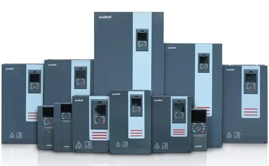
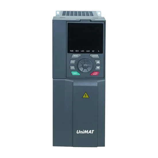
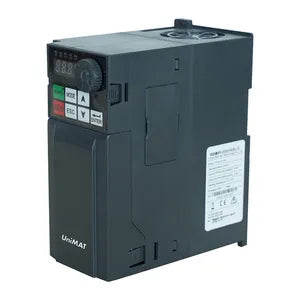
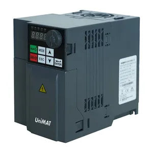
UV 32 SERIES 3 phase vdf variable frequency drive
Product Summary
* Four control modes: constant torque V/f, quadratic load V/f, vector control without PG sensor, energy saving mode
Compact design, exquisite and practical
* Overload capacity: 150% rated output current for 60s, 200% rated output current for 2s
Built-in Modbus communication interface
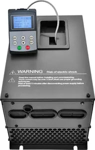
* The panel can be externally connected, easy to use
PCB coating to resist harsh application environments
* The side of the plastic shell product has a removable protective plate,
which supports side-by-side installation
* High-performance vector control using flux and speed
estimation technology
* Wide voltage range design ensures product adaptability
to grid fluctuations
* Advanced independent air duct design, adaptable to
various complex and harsh on-site environments
Strong and Weak Electrical Isolation Design
Adopt srtong & weak electrical isolation Design, to avoid magnetic field
interference and increase service lift.


Heat Dissipation Structure
Independent cooling duct optimization design, from the
original right angle optimization to rounded corner, reduce
the thermal disk accumulation, greatly increase the
efficiency of heat dissipation.
Appearance size:


Product configuration:
| Basic application functions | |
| Low frequency torque boost | The voltage boost and torque boost can increase the low-frequency torque of V/F control and speed sensorless vector control by about 0.1%~30.0% respectively. |
| V/F Curve | Linear type, multi-point type |
| Acceleration and deceleration curve |
Linear or S-shaped acceleration and deceleration; three sets of acceleration and deceleration time; acceleration and deceleration time range: 0-3200s |
| Automatic Voltage Regulation (AVR) | When the grid voltage changes, it can automatically keep the output voltage constant |
| Built-in PID | Closed-loop control system that can easily realize process control |
| DC braking | DC braking range: 0.0Hz-maximum frequency; braking time: 0.0s-20.0s Braking action current value: 0%-100% |
| Jog control | The motor can be started and stopped immediately; the inching frequency setting range is: 0.0-20.0Hz Inching stop mode: deceleration/free/DC braking |
| Frequency Hopping | You can set 3 frequency hopping points and the corresponding frequency hopping range to prevent the inverter from running within the frequency band. |
| Multi-speed | Up to 15 operating frequencies can be set via 4 logic input ports |
| Input Sum | The algebraic operation result of 2 analog inputs is used as the frequency setting, making the frequency setting more flexible |
| 2 sets of motor parameter switching | Two sets of motor parameters can be set and switched freely to match the currently driven motor |
| Inverter protection | Input/output phase loss protection, underload detection, over-torque protection, undervoltage protection, overvoltage protection, overcurrent protection, overheating protection, phase short circuit protection |
| Motor protection | Motor thermal protection, motor current limiting, motor overload, motor short circuit |
| Electrical characteristics | |
| Input voltage | Three-phase AC, 380-480V, 50/60Hz or single-phase AC, 200-240V, 50/60Hz |
| Output voltage | 0-100% input voltage, 0.5Hz - 400Hz |
| Control Mode | Constant torque V/F, quadratic load V/F, sensorless vector control, energy-saving mode |
| On-off level | 1.5kHz - 12kHz The automatic switching frequency adjustment function can be set: when the temperature rises, the switching frequency is automatically reduced After the temperature returns to normal, the switching frequency returns to the initial value |
| Overcurrent capability | 150% rated output current for 60s, 200% rated output current for 2s |
| Control signal | ||
| Frequency setting signal | Integrated operating panel | Membrane switch (button), speed knob (potentiometer) |
| External Signal | UP/DOWN setting, analog input, multi-speed, external panel, serial communication | |
| Start-stop control signal |
Integrated operating panel | RUN, STOP buttons |
| External Signal | Logic input terminal, external panel, serial communication | |
| Protective function | |
| Inverter protection | Input phase loss protection, output phase loss protection, underload detection, over-torque protection, undervoltage protection, overvoltage protection, overcurrent protection, overheating protection, phase short circuit protection |
| Motor protection | Motor thermal protection, motor current limiting, motor overload, motor short circuit |
| Control circuit characteristics | ||
| Internal power supply available |
10V 24V |
10VDC ±5%, maximum current 10mA, for reference potentiometer 24VDC ±5%, maximum current 100mA, for logic input port |
| Analog Input | AI1 | Voltage analog input: 0-5VDC, or 0-10VDC, impedance 30k Current analog input: 0/4-20mADC, impedance 250Ω Resolution: 10-bit A/D conversion Factory default setting: 0-5VDC voltage input |
| AI2 | Voltage analog input: 0-10VDC, or PTC probe input Resolution: 10-bit A/D conversion |
|
| Logic Input | LI1-LI8 | 0-24VDC power supply Positive logic (source), negative logic (sink) are optional, the factory default is negative logic 69 functions are available, including forward, reverse, running, fault reset, multi-speed, etc. 220V 0.4kw-2.2kw and 380V 0.4kw-0.75kw products only have 6 circuits: LI1-LI6 |
| AI1,AI2 Enforce valid input |
In inverters below 11kW (inclusive), AI1 and AI2 can be set as logic inputs. f309 and f310 are mandatory valid inputs, and their configuration functions are always valid during power-on. |
|
| Analog Output | AO1,AO2 | Voltage analog output: 0-10VDC, minimum load impedance is 470Ω Current analog output: 0/4-20mA, maximum load impedance is 700Ω Resolution: 8 bits Output frequency, output current, speed setting, serial output data Multiple functions available 220V 0.4kw-2.2kw and 380V 0.4kw-0.75kw products only have 1 analog output, namely AO1 |
| Logic Output | LO,CLO | Open collector, maximum current 100mA, maximum voltage 30VDC Logic output or pulse output is optional, the factory default setting is logic output Output frequency, output current, speed setting and other output functions are optional |
| Relay output | T1A,T1B,T1C T2A,T2B,T2C |
T1A is normally open, T1B is normally closed, T1C is a common point T2A is normally open, T2B is normally closed, T2C is a common point Contact rating: 5A @ 250VAC, 5A @ 30VDC Fault, alarm, set frequency arrival and other functions are optional T1A defaults to failure, T2A defaults to operation 220V 0.4kw-2.2kw and 380V 0.4kw-0.75kw products only have 1 relay output, namely T1A-T1B-T1C |
| Serial Communication | MODBUS-RTU, 2-wire RS-485, terminal interface | |
| Environmental characteristics | |||
| Protection level | IP20 | environment humidity | 95% no condensation or water accumulation |
| Working temperature/storage temperature | "- 10~40ºC /- 20~60ºC | Altitude | Below 1000m |
| cooling method | Forced air cooling | Installation location | Indoor |

