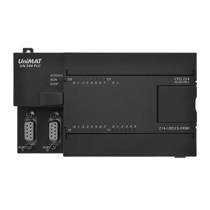
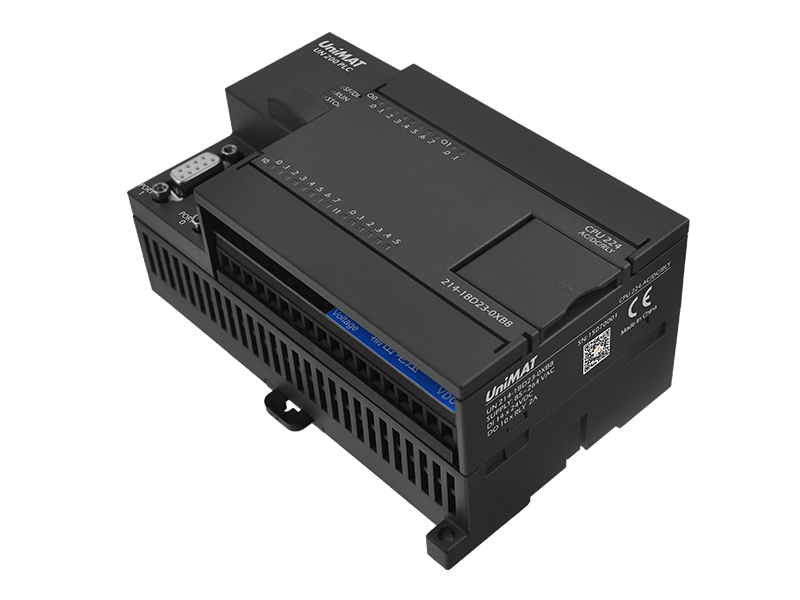
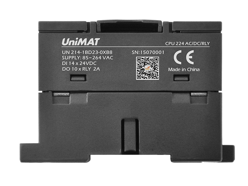
CPU 224-2R AC/DC/RELAY
Program memory:50KB;
2 RS-485 ports, within1standard PPI port;
Built-in digital input:14
|
Physical characteristic |
|
|
Dimensions(W x H x D)(mm) |
140×80×62 |
|
Power consume |
10W |
|
Memory |
|
|
Program memory size |
20K |
|
Data memory |
10K |
|
Back up (by Flash, no need battery) |
keep over 10 years |
|
I/O |
|
|
Local digital inputs |
14 inputs |
|
Local digital outputs |
10 outputs |
|
Digital I/O image size |
256(128 inputs/128 outputs) |
|
Analog I/O image size |
64(32 inputs/32 outputs) |
|
expansion modules allowed (Max) |
7 modules |
|
Pulse catch inputs |
14 |
|
High-speed counters |
6 counters total |
|
Single phase |
6 at 30KHz |
|
Two phase |
4 at 20KHz |
|
Pulse outputs |
- |
|
General |
|
|
Timer |
Total number:256(1ms:4;10ms:16;100ms:236) |
|
Counters |
256 |
|
Internal memory bits stored on power down |
256 |
|
Time interrupts |
2 with1ms resolution |
|
Edge interrupts |
4 up and/or 4 down |
|
Analog adjustment |
2 with 8 bit resolution |
|
Boolean execution speed |
0.08µs per instruction |
|
Real Time Clock |
Built-in |
|
Communications Built-in |
|
|
Ports |
3 RS-485 ports(within1 PPI/Free port,1 free port) |
|
PPI Baud Rates |
9.6,19.2 and 187.5 Kbaud |
|
Freeport Baud Rates |
1.2kbaud to 115.2Kbps |
|
Max. cable length per segment |
With isolated repeater:1000 m up to 187.5kbaud, 1200 mup to 38.4kbaud Without isolated repeater: 50 m |
|
Max. number of stations |
32 per segment, 126 per network |
|
Max. number of masters |
32 |
|
Peer to peer(PPI Master Mode) |
Yes |
|
Power |
|
|
Input voltage |
85 to 264 VAC(47 to 63Hz) |
|
Input current |
60/30mA while CPU only at 120/240VAC |
|
200/100Ma while Max. load at 120/240VAC |
|
|
Inrush current |
20A at 264 VAC |
|
Isolation(field to logic) |
1500 VAC |
|
Hold up time(loss of power) |
10ms at 120/240 VAC |
|
Sensor voltage |
20.4 to 28.8 VDC |
|
Current limit |
1.5A peak,thermal limit non-destructive |
|
Ripple noise (sensor to logic) |
Less than 1 V peak-to-peak |
|
Isolation (sensor to logic) |
Not isolated |
|
CPU Digital Input Specifications |
|
|
Built-in digital input |
14 |
|
Input type |
PNP/NPN |
|
Rated voltage |
24 VDC at 4mA |
|
Max. continuous permissible voltage |
30VDC |
|
Surge voltage |
35 VDC,0.5s |
|
Logic “1” voltage range |
15 to 30 VDC |
|
Logic “0” voltage range |
0 to 5 VDC |
|
Input delay |
Selectable (0.2 to 12.8ms) |
|
Connection of 2-wire proximity sensor (Bero) Premissible leakage current (Max.) |
1mA |
|
Isolation (field to logic) |
Yes |
|
Optical galvanic |
500 VAC for 1minute |
|
Isolation groups |
Refer to Wiring diagram |
|
High Speed Counter (HSC) input rate |
|
|
HSC logic level 1(15 TO 30 VDC) |
20K Hz (Single phase), 10K Hz (Tow phase) |
|
HSC logic level 1(15 TO 26 VDC) |
30K Hz (Single phase), 20K Hz (Tow phase), |
|
Inputs on simultaneously |
all |
|
Cable length Max. |
|
|
Shielded |
500m normal inputs, 50m HSC inputs |
|
unshielded |
300m normal inputs |
|
CPU Digital Output Specifications |
|
|
Built-in outputs |
10 outputs |
|
Output type |
Dry contact |
|
Rated voltage |
24 VDC or 250 VAC |
|
Voltage range |
5 to 30 VDC or 5 to 250 VAC |
|
Surge current (Max.) |
5A for 4s at 10% duty cycle |
|
Logic “1” (Min) |
- |
|
Logic “0” (Max) |
- |
|
Rated current per point(Max.) |
2.0A |
|
Rated current per common(Max) |
10A |
|
Leakage current (Max) |
- |
|
Lamp load (Max) |
30W DC;200W AC |
|
Inductive clamp voltage |
|
|
On State resistance (contact) |
0.2Ω(max. when new) |
|
Isolation |
|
|
Optical (galvanic, field to logic) |
- |
|
logic to contact |
1500 VAC,1minute |
|
Resistance (logic to contact) |
100MΩ |
|
Isolation groups |
Refer to wiring diagram |
|
Delay(Max) |
|
|
Off to on |
- |
|
On to off |
- |
|
Switching |
10ms |
|
Pulse frequency (Max.) |
1Hz |
|
Lifetime mechanical cycles |
10,000,000 (no load) |
|
Lifetime contacts |
100,000 (rated load) |
|
Outputs on simultaneously |
All at 60℃ (horizontal) |
|
All at 50℃ (Vertical) |
|
|
Connecting two outputs in parallel |
No |
|
Cable Length (Shielded) |
500m |
|
Cable Length (unshielded) |
150m |


